
ANSI B4.1 vs ISO 286: Fit Class Equivalents (RC3 = H7/f6, LN2 = H7/p6, FN2 = H7/s6)
ANSI B4.1 vs ISO 286: Fit Class Equivalents (RC3 = H7/f6, LN2 = H7/p6, FN2 = H7/s6)
A drawing from a US customer says "RC3". A drawing from a German supplier says "H7/f6". Both describe the same thing: a shaft that runs freely in a hole with a small, controlled clearance. The two standards were written for two rulers — ANSI B4.1 in thousandths of an inch, ISO 286 in micrometres — and once you know which class maps to which symbol, the numbers line up to within a few microns. This guide gives the full mapping, shows the numbers side by side at one nominal size, explains where the two tables genuinely differ, and says which one belongs on the drawing.
Two rulebooks, one idea
Both standards describe a fit as two tolerance zones compared on one nominal size: the hole's zone and the shaft's. Both are hole basis in practice — the hole is an "H" zone that starts at the nominal size and grows upward, and the shaft is moved to set the fit. The difference is bookkeeping:
- ISO 286 names a fit by letters and grades: H7/f6 means a grade-7 hole with zero lower deviation and a grade-6 shaft sitting slightly below the nominal size. The tables run in micrometres for 25 size ranges up to 500 mm.
- ANSI B4.1 names a fit by class: RC1–RC9 running and sliding, LC1–LC11 locational clearance, LT1–LT6 locational transition, LN1–LN3 locational interference, FN1–FN5 force and shrink. The tables run in thousandths of an inch ("thou", 1 thou = 25.4 µm) for 13 size ranges up to 19.69 in, and each class carries an ABC symbol built from the same letters and grades — RC3 is H7/f6.
That symbol is the bridge. Every ANSI class except four (RC9, LC10, LC11 and FN1, which have no shaft symbol) has a direct ISO twin.
The full mapping
- Running and sliding: RC1 = H5/g4 · RC2 = H6/g5 · RC3 = H7/f6 · RC4 = H8/f7 · RC5 = H8/e7 · RC6 = H9/e8 · RC7 = H9/d8 · RC8 = H10/c9 · RC9 = H11 hole, no symbol shaft
- Locational clearance: LC1 = H6/h5 · LC2 = H7/h6 · LC3 = H8/h7 · LC4 = H10/h9 · LC5 = H7/g6 · LC6 = H9/f8 · LC7 = H10/e9 · LC8 = H10/d9 · LC9 = H11/c10 · LC10 = H12 · LC11 = H13
- Locational transition: LT1 = H7/js6 · LT2 = H8/js7 · LT3 = H7/k6 · LT4 = H8/k7 · LT5 = H7/n6 · LT6 = H7/n7
- Locational interference: LN1 = H6/n5 · LN2 = H7/p6 · LN3 = H7/r6
- Force and shrink: FN1 = H6 hole, no symbol shaft · FN2 = H7/s6 · FN3 = H7/t6 · FN4 = H7/u6 · FN5 = H8/x7
The numbers side by side at Ø1 in = Ø25.4 mm
ANSI values are the published limits for the 0.71–1.19 in range (FN classes: 0.95–1.19 in), converted to micrometres in brackets. ISO values are H7 = +21/0 µm at 25.4 mm with the matching shaft from the ISO 286 calculator.
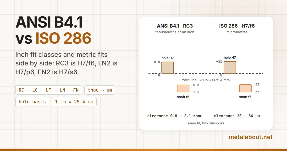
- RC3 vs H7/f6 — ANSI clearance 0.8 – 2.1 thou (20 – 53 µm) · ISO 20 – 54 µm
- RC4 vs H8/f7 — ANSI 0.8 – 2.8 thou (20 – 71 µm) · ISO 20 – 74 µm
- RC7 vs H9/d8 — ANSI 2.5 – 5.7 thou (64 – 145 µm) · ISO 65 – 150 µm
- LC2 vs H7/h6 — ANSI 0 – 1.3 thou (0 – 33 µm) · ISO 0 – 34 µm
- LC5 vs H7/g6 — ANSI 0.3 – 1.6 thou (8 – 41 µm) · ISO 7 – 41 µm
- LT1 vs H7/js6 — ANSI −0.25 / +1.05 thou (−6 / +27 µm) · ISO −6.5 / +27.5 µm
- LT3 vs H7/k6 — ANSI −0.6 / +0.7 thou (−15 / +18 µm) · ISO −15 / +19 µm
- LT5 vs H7/n6 — ANSI −1.1 / +0.2 thou (−28 / +5 µm) · ISO −28 / +6 µm
- LN2 vs H7/p6 — ANSI interference 0 – 1.3 thou (0 – 33 µm) · ISO 1 – 35 µm
- FN2 vs H7/s6 — ANSI interference 0.6 – 1.9 thou (15 – 48 µm) · ISO 14 – 48 µm
- FN4 vs H7/u6 — ANSI interference 1.0 – 2.3 thou (25 – 58 µm) · ISO 27 – 61 µm
Every pair agrees to within about 3 µm — a tenth of a thou. For a running fit or a press fit that is noise; the machinist cannot hold the difference and the part will not know.
Where the two tables genuinely differ
- Size ranges. ANSI has 13 ranges to 19.69 in (FN classes use 25 finer ones); ISO has 25 ranges to 500 mm. A nominal size can sit near the top of one range and near the bottom of the other, and that is where the small differences above come from.
- Rounding. The ANSI tolerance grades were rounded separately from the ISO IT grades. Grade 7 at 0.71–1.19 in is 0.8 thou = 20.3 µm; IT7 at 18–30 mm is 21 µm.
- Hand-adjusted cells. ANSI B4.1 rounds a few cells its own way: RC1 at 0–0.12 in uses a +0.2 thou hole although grade 5 is 0.15 there, and the js shafts of LT1 and LT2 are ± half of a rounded value. The ANSI B4.1 calculator stores the published cells, not values derived from the grade table, for exactly this reason.
- Gaps. LT3 and LT4 are not defined below 0.24 in and FN3 not below 0.95 in. ISO k6 and t6 exist at every size.
- Nominal size. 1 in is 25.4 mm, not 25. Converting a drawing by rounding the nominal size moves the fit into a different ISO range and quietly changes the limits.
Which one goes on the drawing
Quote the standard the drawing is dimensioned in. An inch drawing gets the ANSI class (or its ABC symbol); a millimetre drawing gets the ISO class. Do not write "H7/f6" on an inch drawing and expect the shop to look up ISO tables in inches — there are none. When a legacy inch drawing is converted to metric, take the ISO class with the same letters and grades, convert the nominal size exactly, and check the extremes with both calculators before releasing it. If the part mates with something that stays in inches, keep the inch class.
Worked example: a bronze bushing in a housing
A 1.5 in bushing pressed into a steel housing is class LN2 (H7/p6). From the ANSI B4.1 calculator: hole 1.5000 – 1.5010 in, shaft 1.5010 – 1.5016 in, interference 0 – 1.6 thou (0 – 41 µm). The same bushing on a metric drawing is Ø38.1 H7/p6: hole 38.100 – 38.125 mm, shaft 38.126 – 38.142 mm, interference 1 – 42 µm. The shaft that runs inside the bushing is RC4 (H8/f7) at 1.5 in: clearance 1.0 – 3.6 thou (25 – 91 µm); the ISO twin H8/f7 at 38.1 mm gives 25 – 89 µm. Same parts, same press force, same running clearance — only the ruler changed.
Charts and tools
The ANSI B4.1 fit calculator gives hole and shaft limits in thou, inches and millimetres for all 34 classes with the full class table below the result; the ISO 286 fit calculator does the same in micrometres for 1–500 mm, and each links to the other at the same size. US section sizes are in the W-shape beam chart.